Network Load Balancing cluster for web servers

This manual applies to Windows Server 2012 and describes how to configure Network Load Balancing cluster for web servers.
Consider you have following server setup:
  • DEV-WEB1 – IIS Web Server
  • DEV-WEB2 – IIS Web Server
And following hostnames configured at DNS server:
  • DEV-WEB1: 192.168.7.11
  • DEV-WEB2: 192.168.7.17
  • DEV-WEB: 192.168.7.31
DEV-WEB is a virtual host accessible from the Internet, configure your network Firewall to allow 80 and 443 ports on that host.
DEV-WEB1 and DEV-WEB2 80 and 443 ports should not be available from the outside.

Installing NLB

  1. Connect to DEV-WEB1 via Remote Desktop.
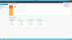
  2. Start Server Manager Dashboard application and select Add Roles and Features from Manage menu:Server Manager - Add Roles and Features
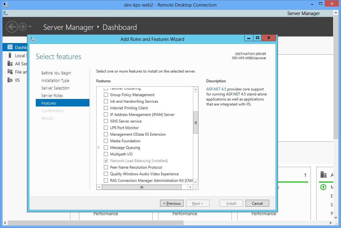
  3. In Features tab of Add Roles and Features Wizard check “Network Load Balancing” and click Install button:Add Roles and Features Wizard - Features
  4. After installation is complete a server restart might be required.
  5. Repeat steps 1-4 for DEV-WEB2 server.

Configuring NLB

  1. Connect to DEV-WEB1 via Remote Desktop.
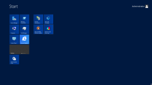
  2. Start Network Load Balacing application from Start menu:Network Load Balancing - Start
  3. Select New from Cluster menu:
  4. Input dev-web1 in Hostname field and click Connect and then Next:Add Host To Cluster - 1
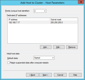
  5. New Cluster : Host Parameters window will show up. Click Next:Add Host To Cluster - 2
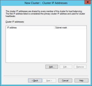
  6. Click Add… button in New Cluster : Cluster IP Addresses window:New Cluster - 3
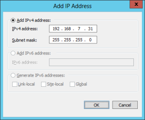
  7. Enter cluster IP address (DEV-WEB host IP address) and click OK:New Cluster - 3.1
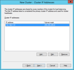
  8. Verify that correct IP address has been added and click Next:New Cluster - 3.2
  9. In New Cluster : Cluster Parameters window enter full Internet host name from which web cluster should be accessible (for example dev-kps-web.kps.local or www.yourcompany.com):New Cluster - 4
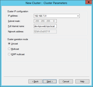
Leave default value of Cluster operation mode  Unicast and click Next.
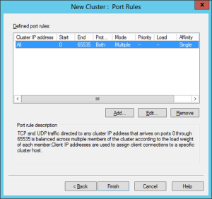
  10. In New Cluster – Portal Rules window click Edit button to edit default port rule:New Cluster - 5
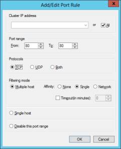
  11. Change port range from 80 to 80, select protocol – TCP, select affinity – Single and click OK:New Cluster - 5.1More information on NLB affinity is available on MSDN: http://technet.microsoft.com/en-us/library/bb687542.aspx. In short Single NLB affinity configures cluster to associate web clients to particular server. For example, when user A will open dev-web page, cluster will assign a user to the server dev-web1 and all ongoing requests from user A will be processed on dev-web1 server.
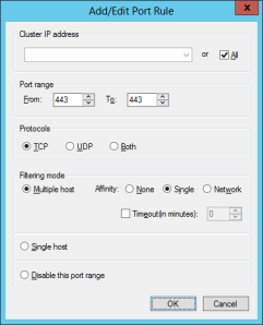
  12. Click Add… button to configure SSL port and set Port range from 443 to 443, select protocol – TCP, select Affinity – Single and click OK:New Cluster - 5.2
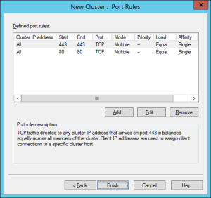
  13. Review that 80 and 443 ports are correctly configured and click Finish:New Cluster - 5.3
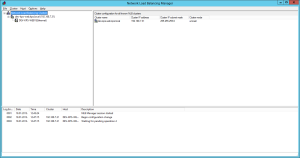
  14. Network Load Balancing Manager will start configuring a cluster. Please, note, that your connection to server might be lost for a few moments, because of Network Interface reconfiguration (additional IP address is added):New Cluster - NLB Pending Cluster
  15. After all pending operations are complete, select Add Host from Cluster menu. Add Host to Cluster wizard will show up.
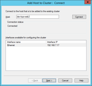
  16. Input second web server host name (dev-web2) in Host field, click Connect and Next:Add Host To Cluster - 1
  17. In Add Host to Cluster : Host Parameters step click Next:Add Host To Cluster - 2
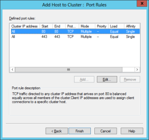
  18. In Add Host to Cluster – Port Rules step verify that 80 and 443 ports are correctly mapped and click Finish:Add Host To Cluster - 3
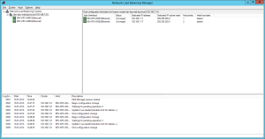
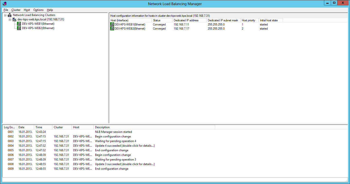
  19. After cluster pending operations are complete your cluster is setup and ready for use:NLB - Cluster
  20. Verify your cluster operation by going to your cluster hostname (dev-kps-web.kps.local in our case):Verify Address
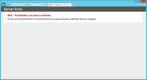
You can see IIS HTTP 403 error response page meaning that request was passed to one of two cluster web servers.
In case you have more than 2 web servers, you may repeat steps 16-19 for all your dev-webN servers.

DISM

How to rip a Windows 7/8 Image using WinPE4.0 and DISM

To begin with, you need downloaded and installed: Windows ADK.WinPE4 & DISM make this sooo much easier now, and support such a large variety of machines out of the box that it made me less Raging for the first time in a very long time. No need for 3rd party tools or guides (unless you get extremely fancy), straight from Microsoft (all of this material is straight from MS infact.)
Guide to WinPE USB Creation: http://technet.microsoft.com/en-us/library/hh825109.aspx

Once ADK is also installed, you will want those deployment tools from its folder on the External.
They are found here:

Code:
C:\Program Files (x86)\Windows Kits\8.0\Assessment and Deployment Kit\Deployment Tools

Copy the Deployment Tools folder to your external drive and name it something you will remember, since this is the core of WADK tools,
I named my copied folder WADK.

Recommended Tools Before Beginning:

  1. An OS that has already been Sysprepped/Unattend prepared!
  2. 2~4GB Flash Drive (Since it is usually fat32, you don’t want to store your 4GB+ file sized image here so just use it for booting PE4.)
  3. External Drive (or another Internal Drive for storing the image to be ripped.)

Boot to the USB WinPE4.0 after your OS has been sysprepped. If you have successfully created a bootable flash drive via the first guide, you should be sitting at a pretty CMD in fast and sexy WinPE4.0.

This should be the default directory you are looking at after it is finished loading:

Code:
X:\Windows\System32

From here, we need to see what WinPE has done about labeling your drives and partitions.

Code:
diskpart
select disk 0
list partition
select partition 0 //only if you use a system partition
assign letter="S" //S for System
select partition 1 //again, would be 0 if there is no partition ahead of this
assign letter="W" //W for Windows
list volume // Look for you external HDD and remember the Drive letter assigned or change it yourself
exit

Now that we have labeled your drives something recognizeable, we then navigate to the WADK folder on your external drive, using the drive letter you just looked up. Mine was assigned to L.

Change root:

Code:
L:

Navigate to DISM folder inside of the WADK copy you made:

Code:
L:\WADK\AMD64\DISM\

Capturing the Image!
Since your OS is already sysprepped and ready to go, you simply capture the correct partition / drive mount

Code:
Dism /Capture-Image /ImageFile:L:\WinImg.wim /CaptureDir:W:\ /Name:"Windows"

Alternatively using UNC and Domain:

Code:
net use Z: \\ServerName\SharedFolder /user:domain\user PASSWORD
Dism /Capture-Image /ImageFile:Z:\MyImages\WinImg.wim /CaptureDir:W:\ /Name:"Windows"

Applying a Captured Image:

Disk Preperation:

Code:
diskpart
select disk 0
clean
create partition primary size=100
format quick fs=ntfs label="System"
assign letter="S"
active
create partition primary
format quick fs=ntfs label="Windows"
assign letter="W"
exit

S:\ Is the 100mb system partition which stores boot info.
W:\ Is the Windows partition.

Whatever drive the Ext HDD is (L:\ for example), navigate to the DIdism SM folder.

Code:
L:

cd L:\WADK\AMD64\DISM

(If you need to find out what drive letter the external hard drive is use DISKPART followed by the “List Volume” command, the “L:” is just the standard way of changing the root drive letter you are working for. You don’t CD L: or CD Q: to change drives, you simply type the drive letter with a colon.)

Apply Windows Image:

Code:
dism /apply-image /imagefile:L:\WinImg.wim /index:1 /ApplyDir:W:\

L:\Directory to Image\ImageFile.WIM, the above Images were just stored on the root of the drive.

Upon fully imaging the drive, you want to create correct boot drive options:
Return to RAM DISK X:\ by typing:

Code:
X:

Should return you to X:\Windows\System32. If not navigate there with CD. Then run BCDBOOT as such:

Code:
bcdboot W:\Windows /l en-US

It will automatically apply to S:\ because of the label. (If it fails for whatever reason you may force application to S drive by using /S S: )

After this it should be good to go and boot the OS.

Sources of Information & Other seriously useful DISM links:
Capturing images with DISM:
http://technet.microsoft.com/en-us/library/hh825072.aspx

Applying images with DISM:
http://technet.microsoft.com/en-us/library/hh824910.aspx

BCBOOT Command Line Options:
http://technet.microsoft.com/en-us/library/hh824874.aspx

Mounting an image and editing files inside it:
http://msdn.microsoft.com/en-us/library/ff794887(v=winembedded.60).aspx

Code:
Note all of this use to be done with a combination of DISM before and ImageX.  ImageX is officially deprecated and DISM now retains all functionality and more.


ISCI Bus sharing issue.

Symptoms

  • You cannot perform a VMware vMotion or a VMware Storage vMotion operation on Microsoft Cluster (MSCS) virtual machines with a shared disk configuration.
  • Virtual machines with SCSI bus sharing enabled cannot be vMotioned or Storage vMotioned while powered on.
  • A cold migration of a virtual machine with Raw Device Mapping (RDM) results in the RDM being copied to a new VMDK file.
Caution: Before performing the proceeding steps, take a full backup of all virtual machines.
Note: VMware recommends performing these steps in a maintenance window as the virtual machines are inaccessible during this time.
To move the underlying backing files of an MSCS virtual machine between datastores:
  1. Shutdown the virtual machine 1.
  2. Remove (but do not delete) the RDM pointers from virtual machine 1.
  3. Cold migrate virtual machine 1 to the destination datastore.
  4. Shutdown the virtual machine 2.
  5. Create new RDM pointers on virtual machine 1.
  6. Power on virtual machine 1.
  7. Verify operating system and application functionality of virtual machine 1.
  8. Remove and delete the RDM pointers from virtual machine 2.
  9. Cold migrate virtual machine 2 to the destination datastore.
  10. Add existing RDM pointers (created in step 5) to virtual machine 2.
  11. Power on virtual machine 2.
  12. Verify cluster functionality.
  13. End maintenance window.
> that it was frowned upon to use an iSCSI connection from within a child VM.
Firstly we need to claim that we can use iSCSI connection in guest VM, but we are not really often use it. In my opinion, it’s not necessary to use iSCSI connection in guest VM. It’s easy to explain the reason.
Why do you want to use iSCSI connection in guest VM?
High IOPS?
Configure iSCSI on Hyper-V host and then use pass through disk can do the same and even better with HBA card.
Larger disk space? More than 2 TB?
Configure iSCSI on Hyper-V host and then use pass through disk can do the same.
lost HA, live migraton?  
You can use pass through disk in a Hyper-V cluster.
The reason why we don’t use iSCSI in guest VM is that virtual machines can only connect to iSCSI devices with a software iSCSI initiator (low performance and cost VM CPU resource), whereas the management operating system will be able to use hardware host-bus adapters (HBAs). The only reason we use iSCSI in guest VM is that we want to create a guest VMs cluster environment, since cluster need shared volumes.
> things have definitely changed, but the matrix of determining the right answer is too much for me.
Yes, new features have been added or changed on Hyper-V in Windows Server 2012, such as Virtual Fibre Channel feature which makes it possible to virtualize workloads and application that require direct access to Fibre Channel-based storage. But I don’t find changes or new features for iSCSI in guest VM. And I think it’s not really necessary.

cannot use SCSI Bus sharing with thin provisioned VMDKs

TIL: You cannot use SCSI Bus sharing with thin provisioned VMDKs

Welcome to my first “today I learned” post. These are posts about details of which I didn’t know about and discovered. Sometimes simple, sometimes complex, but hopefully informative to others.
We have a test SQL 2005 cluster in our vSphere lab that used to power on properly until we did a storage vmotion and converted the VMDK disks to thin format. When trying to power up the VM vCenter spit the following error in the event logs and popped up an error window.
Cannot power Off: VMware ESX Server cannot open the virtual disk,
“/vmfs/volumes/4e60e9a1-f55ef4a3-405f-d485646713b8/MTL1TESQ01/MTL1TESQ01_6.vmdk” for
clustering. Please verify that the virtual disk was created using the ‘thick’ option. Cannot open the
disk ‘/vmfs/volumes/4e60e9a1-f55ef4a3-405f-d485646713b8/MTL1TESQ01/MTL1TESQ01_6.vmdk’
or one of the snapshot disks it depends on. Reason: Thin/TBZ disks cannot be opened in
multiwriter mode..
error
The resolution to this problem is obviously simple, you can either convert the disks to thick.  You can do it via the “inflate” option in the datastore browser or storage vmotion and select the thick option.
Also, if you don’t have any space left on any of your datastores to accommodate the thick disks and you really need to get one system up and running (degraded cluster), then you can always disable SCSI Bus sharing on the SCSI device and power up the VM.